丨 Product IntroductionProduct Introduction:
AK994 RTK board features the 22nm UM982 chip, providing centimeter-level RTK positioning and dual-antenna heading with strong anti-interference capability. Its aluminum enclosure ensures efficient heat dissipation and EMI shielding, making it ideal for stable, reliable positioning in drones, precision agriculture.Features:
1. High-precision positioning: Multi-frequency/multi-constellation (Beidou/GPS) + RTK for centimeter-level accuracy, ideal for surveying/agriculture/engineering
2. Strong signal & anti-interference: Multi-frequency reception resists EMI in urban canyons/vegetated areas, ensuring stable, continuous positioning
3. High real-time performance: Fast data update rate delivers real-time location, fitting dynamic scenarios (autonomous driving/drone mapping)
4. Fast initialization: Quick RTK initialization & short convergence time, boosting work efficiency
5. High compatibility: Supports multiple protocols/formats, easy to integrate with devices/software
6. Flexible dual-mode: Mobile/base station operation + RTCM 3.x calibration data, suitable for diverse scenarios
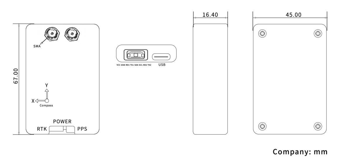
丨 Product Structure
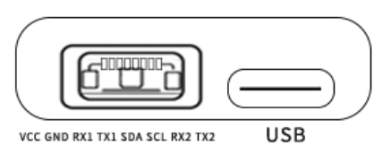
PIN Foot Function
|
NO.
|
Pin Name
|
Describe
|
|
1
|
VCC
|
The power input pin provides the necessary voltage for the device to operate
|
|
2
|
GND
|
Ground pin
|
|
3
|
RX1
|
The receiving end of serial interface 1 is used to receive data sent by external devices through serial port 1.
|
|
4
|
TX1
|
The transmitting end of serial interface 1 is used to send data to external devices through serial port 1.
|
|
5
|
SDA
|
The data pin of the I ² C bus is responsible for data transmission in I ² C communication.
|
|
6
|
SCL
|
The clock pin of the I ² C bus provides a clock signal for synchronous data transmission in I ² C communication.
|
|
7
|
RX2
|
The receiving end of serial interface 2 is used to receive data sent by external devices through serial port 2.
|
|
8
|
TX2
|
The transmitting end of serial interface 2 is used to send data to external devices through serial port 2.
|
|
Chip
characteristics
|
chip
|
UM982
|
|
Working mode
|
BDS: B1I、B2I、B3I
GPS: L1C/A、L2P (Y)、L2C、L5
GLONASS: L1、L2
Galileo: E1、E5a、E5b
QZSS: L1、L2、L5
|
|
Receiving channel
|
1408 channel
|
|
Accuracy
|
Single point positioning (RMS)
|
Plane: 1.5m
|
|
Elevation: 2.5m
|
|
DGPS(RMS)
|
Plane: 0.4m
|
|
Elevation: 0.8m
|
|
RTK(RMS)
|
Flat: 0.8cm+1ppm
|
|
Elevation: 1.5cm+1ppm
|
|
Directional accuracy (RMS)
|
0.2 degrees/1m baseline
|
|
Time accuracy (RMS)
|
20ns
|
|
Speed accuracy (RMS)
|
0.2 m/s
|
|
Observation accuracy (RMS)
|
BDS
|
GPS
|
GLONASS
|
Galileo
|
|
B1I/B1C/L1 C/A/E1/G1 pseudorange
|
10cm
|
10cm
|
10cm
|
10cm
|
|
B1I/B1C/L1 C/A/E1/G1 carrier phase
|
1mm
|
1mm
|
1mm
|
1mm
|
|
B3I/L2P (Y)/L2C/G2 pseudorange
|
10cm
|
10cm
|
10cm
|
10cm
|
|
B3I/L2P (Y)/L2C/G2 carrier phase
|
1mm
|
1mm
|
1mm
|
1mm
|
|
B2I/L5/E5a/E5b pseudorange
|
10cm
|
10cm
|
10cm
|
10cm
|
|
B2I/L5/E5a/E5b carrier phase
|
1mm
|
1mm
|
1mm
|
1mm
|
|
First positioning time TTFF
|
cold boot
|
<20s
|
|
Initialization time
|
<5s (typical value)
|
|
Initialize reliability
|
>99.9%
|
|
Output data
|
Baud rate
|
115200bps (default) [Optional: 4800-921600]
|
|
Output interface
|
TTL/USB
|
|
Output Protocol
|
NMEA0183、RTCM 3.3
|
|
Data update rate
|
1Hz-20Hz (default 1Hz)
|
|
Differential data
|
RTCM 3.3/3.2/3.1/3.0
|
|
Carrier phase output
|
Support, output RAWX statement
|
|
FLASH
|
built-in
|
|
Electrical
specifications
|
working voltage
|
3~5.5V DC
|
|
power waste
|
<800mW
|
|
Physical
parameters
|
size
|
67*45*16.4mm
|
|
weight
|
31.2g
|
|
Shell material
|
Aluminum
|
|
Connector
|
TYPE-C/ SH1.00mm 6pin
|
|
Antenna connector
|
SMA straight head*2
|
|
Environment
|
working temperature
|
-35℃-80℃
|
|
Storage temperature
|
-40℃-85℃
|
|
Compass
|
compass
|
IST8310
|
Packaging and Delivery: